Industrial sewing machine conversion - revisited
My original conversion worked quite well, but the limiting factor was the motor.
At higher speeds the 'flywheel effect' kept the momentum and material penetration going, but at lower speed and starting up the motor struggled, even with the gearing ratio I had created.
This came to a head when stitching military rip-stop canvas in quadruple layers, making dog training dummies. Not only was the material thick, but the short stitch runs before turning the material meant the speed needed to be low.
I drilled and tapped the drive wheel and fixed a hand crank to get through this job, not ideal but worked.
The alternative motors came down to either a direct drive servo unit or a more traditional belt and pully servo drive.
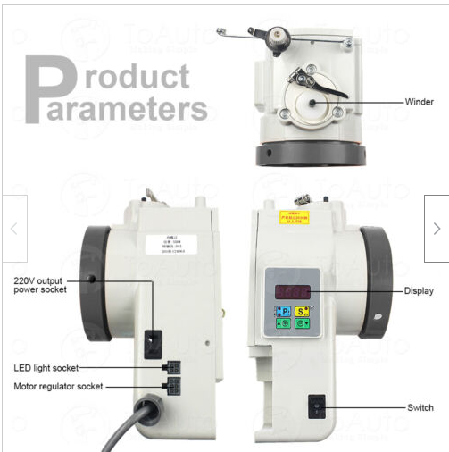
The direct drive unit left, was initially more attractive, it would replace the drive wheel and fix directly to the back of the machine, driving the shaft.
The problem I could foresee however was the minimum speed was set at about 400rpm and with no intermediate gearing would be quite fast at even the slowest speed.
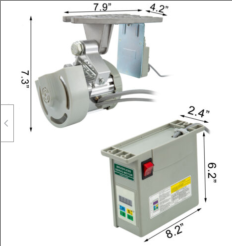
The more traditional belt drive unit right, originally made for mounting under an industrial sewing table, offered better gearing posibilities but some work to achieve mounting.
The pricing of the belt drive over the direct drive, for the same 750W power, was about half.
After much thought, not least what the vague dimensions shown would amount to in reality, I went for the belt drive.
I figured that even if I mounted off the machine I would be able to utilise the drive wheel I had made and keep the gearing advantage.
As it turned out, this was the right choice.
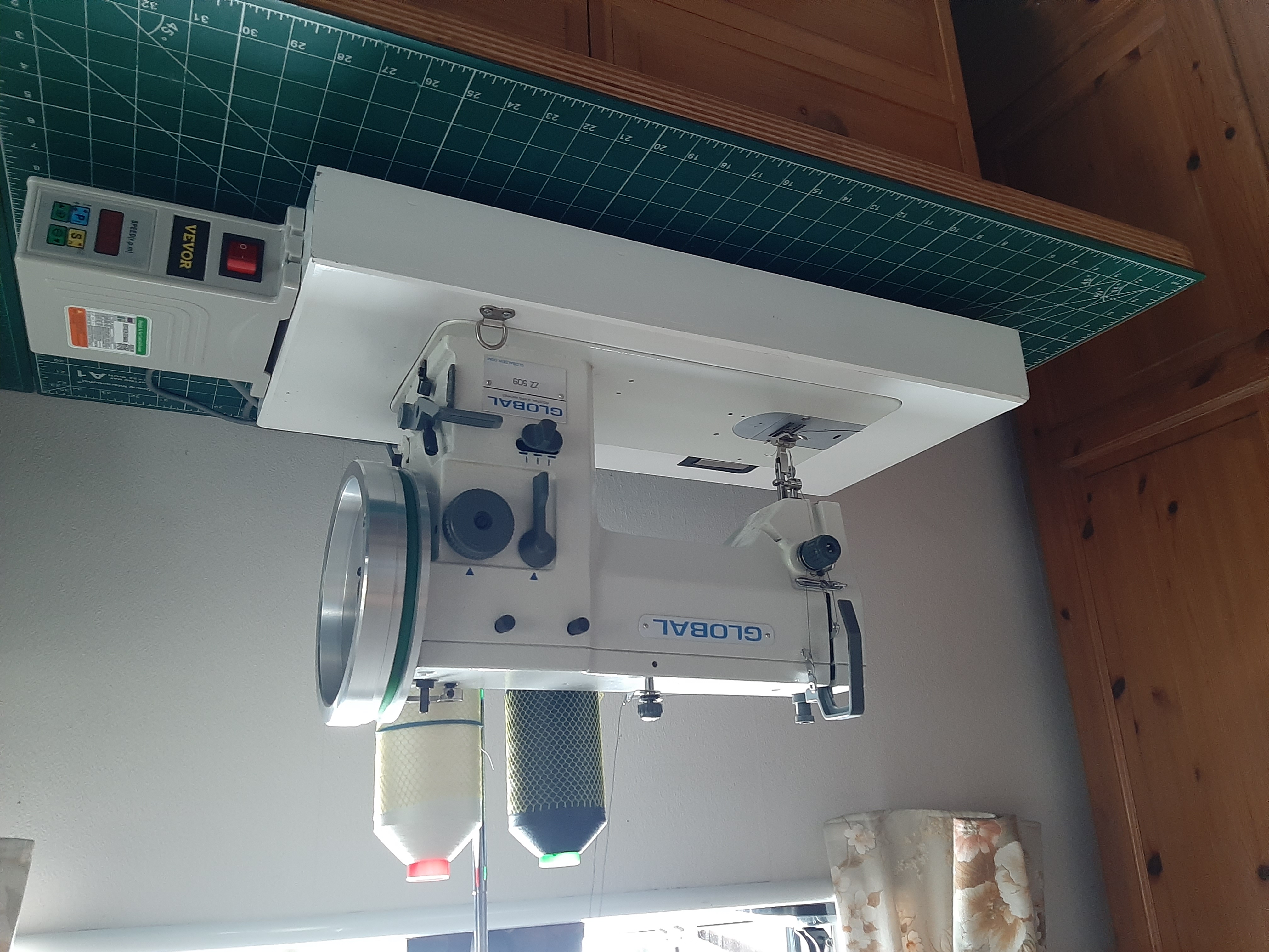
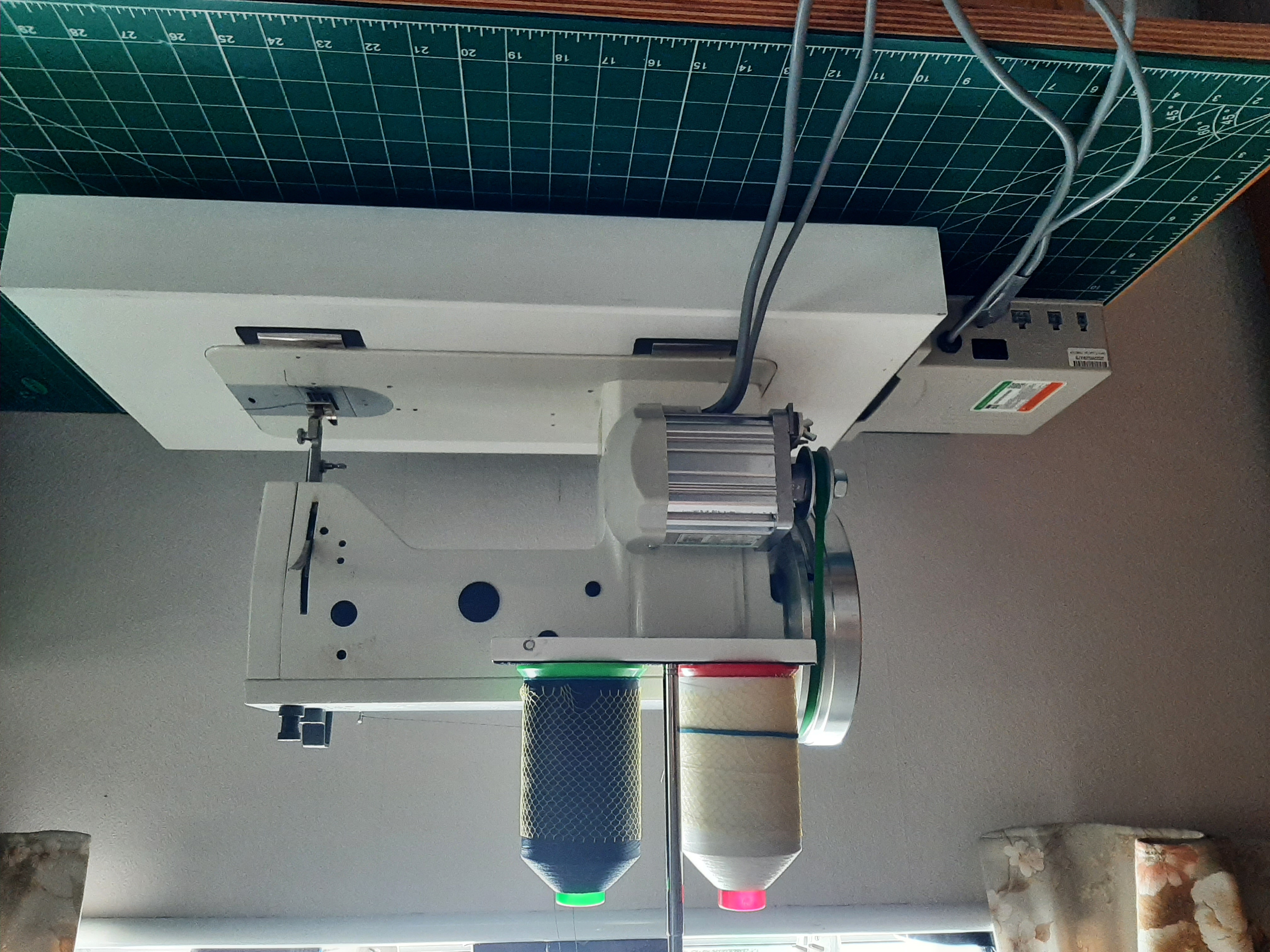
The motor was very light, being all aluminium construction. It was also quite small when removed from mounting brackets and clamps, fitting behind the machine upright without extending into the sewing area.
I made a 9mm thick mounting bracket which bolted to the motor with clamping screws placed to utilise the original motor mount.
Using the smaller nominally 2" pulley provided, the lower 400 rpm motor speed produced an approx 50 spm needle speed, ie an 8:1 reduction.
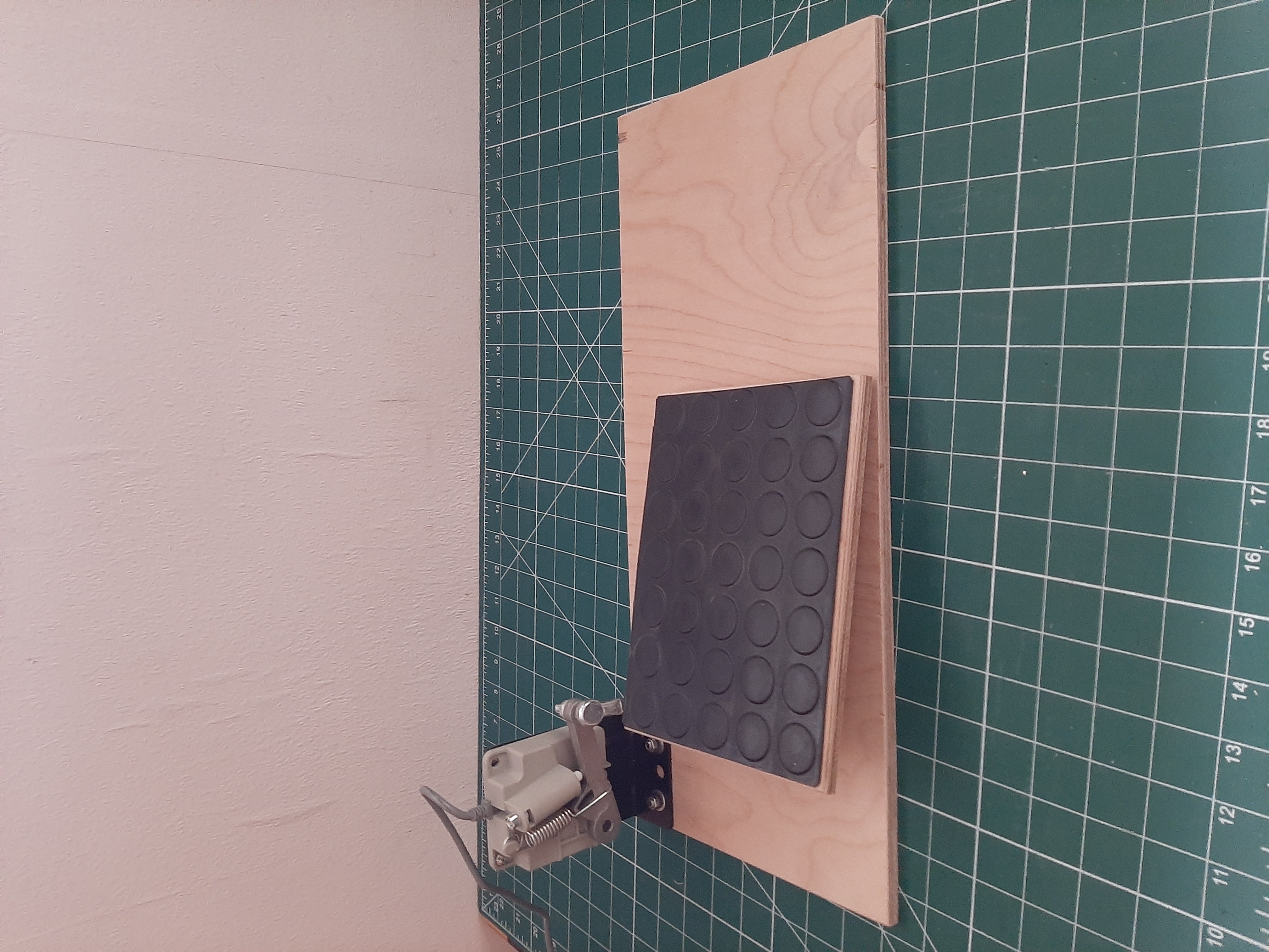
The next issue was a foot control.
The motor kit assumed an industrial table with fitted treadle type foot plate.
The speed control was a standard 'pull down' operated Hall Effect unit, without a great deal of movement. However that would be compensated for by being able to cap maximum speed accurately.
I extended the control lead and made a foot operated plate linked to the speed control.
Initial results are very promising, some items to test fully in the pipeline.
